Chat with us, powered by LiveChat
Precision Graphite Solutions

LEARN SOMETHING NEW

Graphel Carbon Products’ Blog Nationwide

Stay Informed

At Graphel Carbon Products, we know that you’re concerned about the latest industry trends and products worldwide. That’s why we have a blog about graphite and EDM solutions. Take a look through our articles down below to learn something new, then contact us with questions.

Author: Graphel

Week 8: Copper vs. Graphite

From Entegris| POCO Materials   Article by Jerry Mercer


THE SEARCH CONTINUES: GRAPHITE OR COPPER, WHICH TO CHOOSE?

When determining the best EDM electrode material to use, the debate between graphite and copper has been long standing and is yet to be resolved. Many argue that graphite is the preferred electrode material while others stand firm with their preference for copper. Depending on the geographical region, the answer is most always the same. In North America, the preferred electrode material has shifted from copper in the beginning to graphite today. For Europe and Asia, some may argue that copper is the preferred material; however the use of graphite in these regions is steadily increasing. Without question, as depicted in Chart 1, graphite is the predominant material in the United States with at least 95% of electrodes being produced from this material. Steady increases of the use of graphite in Europe over the past decade have resulted in an electrode material ratio of 75% graphite/ 25% copper. Asia follows closely behind with estimations of 45% graphite/55% copper with the use of graphite continually rising. With over 70% of the global market using graphite electrode materials over copper today, perhaps the better question is not which is the best EDM electrode material to use, but instead what is causing this global change in the industry? To answer this, we must first identify the differences of each material to one another.

Graphite Electrode Usage Chart

Continue reading

Week 7: Electrode Material Effect on CNC EDM

From Entegris| POCO Materials   Article by Jerry Mercer


INTRODUCTION

Unrivaled advancements in EDM technologies have become an intrinsic means of ensuring success in today’s global competitive environment. Shops today must find a method of reducing manufacturing costs while boosting productivity and providing a quality mold on time while meeting ever-increasing demands in customer specifications. Oftentimes this entails upgrading capital equipment to current technological capabilities. This article will examine the use of adaptive control and introduce the effects that an electrode material may have on the efficiencies of this function. Further, it will describe the details of a test conducted with an identical rib detail machined from materials of two different classifications programmed to complete the same task.

Continue reading

Week 6: Total Cost Of Ownership And Productivity Analysis For EDM

From Entegris POCO Materials    Article by Jerry Mercer

INTRODUCTION

In the competitive moldmaking industry, throughput is the key to keeping production costs competitive. Shops want to increase productivity while maintaining profitable margins on their sinker EDM-related operations. Part of management’s strategy is often the inclusion of new equipment and technology. Investing in technology is as important to global competitiveness as optimizing asset ownership.

Continue reading

Week 5: Sometimes Graphite Just Isn’t Enough

From Entegris POCO        Article by Jerry Mercer

INTRODUCTION

Common work metals, such as tool steels, are easy to EDM with traditional graphite electrodes.

Others are not. Because of their unique characteristics, questions continue to arise about effectively EDMing materials like beryllium copper, titanium, and tungsten carbide. Even though traditional graphite electrodes do an admirable job of EDMing these exotic metals, there is a more efficient way.

For common metals, the main criteria for selecting an electrode material may center on particle size, strengths, etc. While these characteristics are important to consider when EDMing exotic metals, the electrical resistivity — or the resistance to the current applied to the electrode— is the determining factor in choosing an electrode material. The resistivity value determines how much of the spark energy can pass through the electrode material and is available to attack the workpiece.Graphite for EDM Electrodes

GRAPHITE ELECTRODES

Graphite is relatively inexpensive and is easily machinable when creating detailed electrodes. Porosity is inherent in the graphite microstructure. This porosity acts as an insulator to the electrical current as it travels through the electrode and therefore raises the resistivity value of the material.


Copper impregnated graphite for EDM
The open porosity of graphite (top) is key to the impregnation process. Copper graphite is formed when copper fills the pores (bottom).

Typically, this higher resistivity is not an issue when working with standard metals. Unfortunately, the same is not true with exotic metals. Graphite electrodes can still get the job done, but with their higher resistivity values, the use of traditional graphite electrodes could actually interfere with the most efficient EDM performance.

COPPER IMPREGNATED GRAPHITE

So where do we find an electrode material with a low resistivity value that will allow us to maximize the amount of energy we can pass to an exotic workmetal? Copper is one of the most conductive materials available on the market today. However, it is not the best material for detailed electrodes because it is relatively soft, creating a machining disadvantage, and its low melting point often results in increased electrode wear.

So now what? How about the best of both worlds? Copper impregnated graphite. Copper impregnation of graphite creates a material with the qualities of each of its constituents. Copper graphite is easy to machine with even the most complex details. The presence of copper in the open porosity lowers the electrical resistivity of the electrode, maximizing the flow of energy into the workpiece and increasing the metal removal rate. The graphite element means the electrode is resistant to wear in even the most challenging of EDM scenarios, resulting in fewer electrodes needed per job.

THERMAL CONDUCTIVITY AND MELTING TEMPERATURE

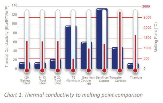
What effect does thermal conductivity have on the workmetal? Since EDM is a thermal process, the melting temperature and the thermal conductivity of the work metal— more so than its hardness — can create difficulties for the EDMer.

Some metals—such as copper and copper alloys— have a low melting point, but are such good thermal conductors that the spark energy is so quickly dissipated throughout the workpiece that very little remains in the EDM cut.

Some other metals— such as tungsten carbide— have higher melting points and lower thermal conductivity. The issue here is that higher temperatures are needed to maintain efficient metal removal; however, these higher temperatures run the risk of damage to the workpiece.

The metal’s melting temperature and thermal conductivity value require the EDMer to make adjustments that differ from one work metal to another. If different exotic metals are burned with the same EDM program, the results could be vastly different.

As an example, copper alloys are routinely chosen for injection inserts because their high thermal conductivity allows the alloy to rapidly transfer more thermal energy away from the molded part in a reduced amount of time. Higher diffusivity allows these materials to maintain a thermal symmetry or balance much more rapidly when there are temperature changes in the mold.

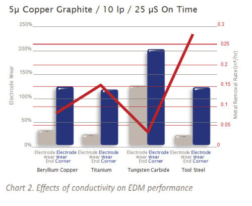
For the molder, this is a distinct advantage. But for the moldmaker, the higher thermal conductivity of the copper alloys means that the thermal energy of the EDM spark is dissipated throughout the work- piece very rapidly and results in less spark intensity being applied in the EDM cut. Since the intensity of the spark is reduced in the cut, it goes without saying that the corresponding metal removal rates are also reduced, Charts 1 and 2.

Copper Graphite Performance for EDM ElectrodesCopper Graphite Performance for EDM Electrodes

EDM PROCESS WITH EXOTIC METALS

The process for EDMing standard metals varies greatly from that required to EDM exotic metals. With standard metals, the current flow is directed from the workpiece to the electrode (also known as positive polarity to the electrode).

A long on-time and high amperage leads to a high metal removal rate and a good replating situation, which reduces electrode wear. But when machining exotic metals with copper graphite electrodes, to operate at peak efficiency, changes have to be made to polarity, on-time, and amperage.

Polarity

With the characteristics of exotic metals, the current flow has to be reversed and directed to the workpiece, or in other words, negative polarity to the electrode. This maximizes the spark energy going into the cut, and therefore, focuses as much heat as possible under the spark.

In comparison to positive polarity, negative polarity will cause an increase in electrode wear, but the increase in the metal removal rate more than outweighs the loss in wear resistance.


On-time

With the higher conductivity characteristics of exotic metals, we have to be cautious with the on-time to prevent a portion of the spark time from being nonproductive. For instance, an optimized on-time for a standard metal may be 50 microseconds— this may not be the same for a highly conductive workpiece.

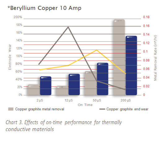
If we were to use an on-time of 50 microseconds with this cut, only a small portion of it will actually remove metal. The remaining portion will not benefit the EDM process in any way because the conductivity of the workpiece pulls the energy away from the cut. In this scenario, metal removal would be much more productive when on-time is reduced to only that portion of time that actually removes metal, Chart 3. As a general rule, an optimal on-time setting for exotic metals would be between 12–20 microseconds.

Graphite Copper performance for EDM

Amperage

It is a common belief that when machining metals with higher conductivity values, we can simply increase the amperage to increase the metal removal rate. While this may be true in some metals, we must also be aware that others—carbides for example—are more susceptible to damage when using excessively high amperage.

The higher amperage should only be used when the characteristics of the exotic metal show to have a high thermal conductivity that will disperse the increased energy to areas outside of the cut. Remember that with negative polarity and a material with lower resistivity, the spark intensity is increased in the cut. As a result, there may not even be a need to increase the amperage to maintain an efficient metal removal rate.


YOU GET WHAT YOU PAY FOR

In today’s competitive marketplace, the temptation is strong to cut corners to reduce manufacturing costs, and it seems the electrode material is the first to suffer. As stated above, when dealing with exotic materials, it is imperative that the correct electrode material be used. Too often, purchase cost is the determining factor in choosing an electrode material. It is becoming commonplace that job requirements exceed the performance capabilities of the more economical graphites, resulting in poor performance and an actual increase in manufacturing costs.

While copper impregnated graphite is more costly than standard graphite, the old adage “You get what you pay for” holds very true. When the conductivity properties of copper and the wear resistance of graphite are combined, they create a material uniquely capable of EDMing exotic metals efficiently. Copper graphite electrodes provide a superior combination of metal removal and wear resistance, resulting in a more stable EDM process and an overall reduction in cost of production.

FOR MORE INFORMATION

Please call your local distributor to learn what our premium graphite solutions can do for you. Visit poco.entegris.com/distributors for the location nearest you.

Week 4 Dealing with Graphite Dust

From Entegris Poco     Article by Jerry Mercer


INTRODUCTION

Dust, a common household word that can be defined as a finely powdered substance of various matters often suspended in the air. This is no different with the dust generated when machining EDM electrodes. Anyone that has machined graphite knows that the particles generated from the machining process are very fine and have a tendency to remain airborne. However, unlike common household dust, graphite dust has characteristics that must be taken into consideration. This article will discuss these characteristics and answer often asked questions in dealing with graphite dust.


HAZARD OR NUISANCE

Perhaps the most common concern when dealing with graphite dust is if it is considered a hazard to the human body. To answer this, we must first understand that there are two types of graphite– natural and synthetic. The graphite used to fabricate EDM electrodes, and thus produce machining dust is synthetic graphite and considered to be a biologically inert material that produces dust classified as a nuisance instead of a hazard. The most common isotope in graphite is carbon and since the human body itself is primarily carbon it is very compatible to the inert carbon material in synthetic graphite. Not recognizing this as a foreign substance, the human body will not attempt to reject it.1

While every measure should be taken to capture the dust at the source, this is virtually impossible and some amount will surely escape into the surrounding atmosphere. Due to the miniscule size of the dust particles, these may not be visible to the human eye. Graphite dust may be irritating to the eyes and could possibly cause stinging, watering, and redness. Contact with this dust may be abrasive and mildly annoying to the skin, but absorption is unlikely.2 There is always some form of health concern associated with any type of overexposure and a nuisance dust is no different. For this reason, exposure guidelines for graphite dust have been determined and identified in the Material Safety Data Sheet (SDS).

As identified by the American Conference of Governmental Industrial Hygienists (ACGIH), the exposure guideline for time-weighted average (TWA) for graphite dust over an eight hour period is 10 mg/m3 total.3  At this concentration, the graphite dust would be thick enough to hinder visibility. Having a concentration of this magnitude in a manufacturing environment is unlikely, especially if some type of dust collection system is in use.

Excessive exposure to graphite dust over extended periods of time can cause a chronic and more serious condition known as graphitosis, which is a form of pneumoconiosis. This condition arises when inhaled particles of graphite are retained in the lungs and bronchi. Hazards such as graphitosis have typically been associated with natural graphite, but have been associated with synthetic graphite in extremely rare instances.1 Natural graphite contains crystalline silica that precipitates graphitosis. This is not found in synthetic graphite or any dust produced by machining synthetic graphite. Long-term inhalation studies in rodents have not shown graphite dust to have serious health effects, however, air quality samples should be taken regularly to monitor the concentration of airborne graphite dust.

NOTE: Special considerations should be taken into account when dealing with graphite impregnated with other materials, such as copper or tungsten. Follow the health and safety guidelines for the material that has been impregnated into the graphite.


DUST COLLECTION

Aside from the need to capture machining dust to maintain a clean shop environment and protect employees, another critical need for dust collection is to prevent the graphite particles from entering into electrical housings, control panels, and switch boxes. By nature, synthetic graphite is electrically conductive and could create a myriad of problems if allowed to accumulate in areas that have a tendency to “short out” when in contact with foreign conductive materials.

There are primarily two methods for controlling graphite dust during the electrode fabrication process. The first method is to use high air velocity with a dust collector. High speed machining centers designed for machining graphite come already equipped with a dust collection system that evacuates the dust with a powerful vacuum. However, conventional machining centers such as mills, band saws, or grinders must be equipped with a type of secondary collection system. Portable units are ideal for shops that only do a limited amount of graphite machining since the unit can be moved from one machine to another as needed. Contrary to common belief, an “off the shelf” shop vacuum system is not adequate for graphite dust as the filtering system is generally not suited to collect the fine particles of graphite. To be efficient, a portable vacuum system must be equipped with a High-Efficiency Particulate Air (HEPA) filter that satisfies certain governmental standards of efficiency. For a filter to be qualified as a HEPA filter by government standards, it must be capable of removing 99.97% of all particulate matter in excess of 0.3 microns.

The best system for shops heavily engaged in graphite machining is a fixed unit with sufficient vacuum to draw the dust from the machine, through the duct work, and into a collection bin. The recommended speed for capturing dust at the machining center is a minimum air velocity of 500 feet per minute. Once the dust enters the duct work, there should be a minimum air velocity of 2000 feet per minute to prevent the dust from settling out of the air stream prior to entering the collection bin. The air velocity is determined by the amount of graphite dust in the air and relates to the rate of material removed at each machine. A recommended source of information for designing dust collection systems is “Industrial Ventilation: A Manual of Recommended Practice by the American Conference of Governmental Industrial Hygienists”.

The second method for dust control is to use a “wet” system to saturate the area around the cutter part with a liquid to prevent dust from entering into the surrounding atmosphere. The dust comes in contact with the fluid being used and is flushed away to a collection unit. While this can be an effective use of dust control, one must keep in mind the ability of the fluid to “wick” or be absorbed into the electrode material being machined. If this occurs, then the fluid must be removed prior to the electrode being placed in the EDM or it could contaminate the dielectric oil. In a wet-style dust collection system, a water-base solution should be used as this fluid does not wick into the graphite as easily as an oil-based solution.

Regardless of the type of solution used, the electrode material should be allowed to dry sufficiently prior to EDM. In order to expedite this process, the material could be placed in a convection oven for approximately one hour at a temperature slightly exceeding the vaporization point of the solution. In no case, should the oven temperature exceed 204°C (400°F) as this causes the material to oxidize and erode away. As an added note, compressed air should never be used to dry off an electrode as the air pressure only serves to force the fluid into the structure of the electrode.


EXPLOSIVE POTENTIAL OF GRAPHITE DUST

When we think of controlling dust in the workplace we often think of how to reduce or eliminate the potential of inhaling dust particles to prevent health issues. Unfortunately, the consequences of a fire or explosion caused by accumulated dust in the workplace can be far greater.

Dust explosions in manufacturing plants over the past decade have certainly gained media attention as these tragic events resulted in needless loss of life and property. The devastation of these events also caught the attention of the Occupational Safety and Health Administration (OSHA) who in 2008, issued OSHA Directive CPL 03-00-008 which states, “This directive contains policies and procedures for inspecting workplaces that create or handle combustible dusts. In some circumstances, these dusts may cause a deflagration, other fires, or an explosion.”4 As a result of this directive, facilities that generate dust through a number of processes, to include machining graphite should conduct an assessment of their practices to determine the potential of a dust explosion and develop practices to lessen the probability of this occurring. The primary objective of this assessment is to identify if dust particles are combustible and in concentrations sufficient to ignite.

Combustible dust is identified as, “Any finely divided solid material that is 420 microns or smaller in diameter (material passing a U.S. No. 40 Standard Sieve) and presents a fire or explosion hazard when dispersed and ignited in air.”5 The elements of fire include fuel, oxygen, and ignition. A dust fire or deflagration occurs when sufficient concentrations of fine particulates are suspended in air and then exposed to a source of ignition such as a spark or welding igniter. This ultimately results in dust ignition or combustion.

In regard to a dust explosion, two additional elements are added. These are dispersion and confinement. If the dust is dispersed in sufficient volume or a dust fire is in a confined area, then the potential of this developing into an explosion is significantly increased. Controlling any one of these elements will essentially eliminate the potential of a dust explosion. To overcome the potential of a graphite dust explosion, the industry has primarily relied on controlling the element of fuel by removing dust at the source through effective vacuum systems. However, this does not minimize the need to address each element and determine practices to mitigate its contribution to an explosion.

To increase its effectiveness in controlling the dust and reducing the fire or explosion potential, all dust control equipment involved in handling graphite dust should have explosion relief vents, an explosion suppression system, or an oxygen-deficient environment. Having adequate general ventilation is the first step and should be sufficient to also limit the employee exposure to airborne contaminants such as graphite dust particles.3


EXPLOSIBILITY TESTING

It is beyond the scope of this article to identify the full testing process in determining the explosive nature of graphite, however, we have conducted tests of graphite dust generated from onsite machining operations. The results of this testing [below] provide an indication of the limits for the graphite dust generated. However, due to variability in conditions, each shop will need to perform the explosibility testing for their specific conditions to have correct data to make a valid assessment of their activities.

The results of this testing indicate that the graphite dust used in these tests are hard to ignite even with low-moisture content and high-concentration levels where 98.5% of the particles are less than 500 micron in size. To reiterate, combustible dust is defined as a solid particle being 420 micron or smaller that can be ignited. In a shop environment, at the concentration levels of these tests, the graphite dust would most likely be thick enough to hinder visibility. Therefore, the bottom line is that the potential of experiencing a graphite fire or explosion is minimal as long as good ventilation and sufficient dust collection is present, and effective cleaning and maintenance programs are utilized.

In some cases, additional information can be provided by the manufacturer. One possible source for information on combustibility is the SDS for the material. Hazard statements should be contained in each SDS that identify if the material is a combustible product in its present form or a future transformed form. The SDS should also identify the exposure controls limits as well as the Hazardous Material Information System (HIMS) and National Fire Protection Agency (NFPA) rating. Contact your graphite supplier for a copy of the SDS for your specific material.


CONCLUSION

Dust is an ever present condition in a manufacturing environment generated by a myriad of processes that include production equipment, material handling, and machining. The creation of this dust does not inevitably lead to safety and health risks if accumulation levels are kept within limits through effective housekeeping and dust collection practices. However, when excessive amounts of dust are allowed to accumulate and then introduced to an ignition source, the results can be catastrophic.

Although our testing has shown that graphite dust is hard to ignite, this does not release us from our responsibility to continually improve how we deal with graphite dust. Recent times have seen the development of practices meant to improve the ability to identify an explosion risk. These practices often include safety monitoring equipment, improved dust collection systems, and the implementation of an effective safety program that offers good house- keeping practices and an efficient preventive maintenance program. While a dust fire or explosion cannot be completely eliminated, the use of these practices significantly reduces the possibility of this occurring. Being aware of the elements for a dust fire or explosion, knowing the explosive potential of the graphite dust and what resources are available for further information greatly improves the ability to identify potential risks and eliminate them before it is too late.


EXPLOSIBILITY POTENTIAL TEST RESULTS

TEST CONDITIONS

20-Liter Sphere

Particle Size Distribution
2-5 KJ Chemical Igniters 4-100 J electric matches 26.0% less than 45 micron
Rebound Nozzle Dust Dispersion System 34.2% less than 75 Micron

70.1% less than 125 Micron

 Pmax 6.2 bar 0.0 bar 93.0% less than 250 micron
(dP/dt)max 136 bar/s 0 bar/s 98.5% less than 500 micron
Kst 37 m•bars/s 0 m•bars/s
Duration of combustion 52 ms 0 ms
Moisture content tested 2.40%

Overall rating:

Hard to ignite

2.40%

Overall rating:

Hard to ignite

Weight % <75 micron 34.70% 34.70%
Bulk density 43.7lb/ft^3 43.7lb/ft^3

References


1 Controlling Graphite Dust During the Machining Process; Moldmaking Technology, January 2000

2 Graphite electrodes used in electrical discharge machining generate a lot of dust, what to do with it? http://global-plas- tic-injection-molding.com/graphite-electrical-dis-

charge-machining.html

3 SDS: Poco Graphite Synthetic EDM Grade

4 OSHA Instruction, Directive Number: CPL 03-00-008, Combustible Dust National Emphasis Program (reissued), http://www.osha.gov/pls/oshaweb/owadisp. show_document?p_table=directives&p_id=3830


5 National Fire Protection Association (NFPA). NFPA 654. Standard for the Prevention of Fire and Dust Explosions from the Manufacturing, Processing, and Handling of Combustible Particulate Solids. 2006 Edition NFPA Inc. Quincy, Mass. 2006. http://www.nfpa.org


FOR MORE INFORMATION

Please call your local distributor to learn what our premium graphite solutions can do for you. Visit poco.entegris.com/ distributors for the location nearest you.

Week 3 Electrode Effect on a Quality EDM Finish

From Entegris Poco     Article by Jerry Mercer

INTRODUCTION

A common belief in the moldmaking industry is that a lower quality electrode material can be used to produce superior surface finishes if a high quality EDM machine is used. While the technologies of the newer generation EDM sinkers have allowed the EDMer to become more proficient in the application, this technology only goes so far when it comes to producing fine surface finishes economically with low quality electrode materials. True, improved EDM sinker technologies have the ability to monitor the condition of the EDM process and make adjustments to run more efficiently. However, these changes are generally limited to optimizing the roughing stage or to eliminating arcing in the EDM cavity. Often, the production of fine surface finishes in the cavity does not come with the technological improvements of the EDM sinker unless a higher quality electrode material is used.

MATERIAL CHARACTERISTICS

In general, the material characteristics of the electrode play a much larger role in achieving a fine surface finish than one might think. When we think of fine finishes, we may

Figure 1 EDM Materials
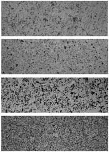
Figure 1: Four materials being supplied to the industry as high quality electrode material

envision something similar to a glossy finish that reflects light very easily. Conversely, in today’s mold design a fine finish means more than a polished surface. Many of the molds that are currently being produced require a textured finish that must be consistent throughout the cavity. In light of this, any variation of the texture within the cavity stipulates that the finish be retextured through additional EDM processes, acid etching, and so forth. These actions require additional time and increase costs — therefore, limiting the profitability of the application.

With a high quality electrode material, the cavity surface finish is one area where opportunity exists for saving time and costs while still producing a quality mold. A high quality electrode material can be thought of as a material of small particle size and having a consistent microstructure and uniformity between the particle size and porosity.

For example, Figure 1 illustrates four materials being supplied to the industry as a high quality electrode material. While the material characteristics may be perceived as a quality material by the manufacturer, the surface finishes obtained from these materials will vary significantly under the same EDM parameters.

As previously stated, the microstructure of the electrode material plays a vital role in the ability to achieve a quality EDM finish in the cavity. As the EDM cavity is a replication of the electrode microstructure, the ability to obtain fine surface finishes is limited with materials of inconsistent structures. If a low- to mid-quality electrode material is used in a textured cavity, there is an increased risk that the texture will be uneven.

Also, since various components of the mold are often outsourced to different companies, this increases the potential that the textured finish will be mismatched.

If this occurs, the most common means to rectify the situation is to acid etch the cavity. In the etching process, the EDM finish must first be removed, therefore, allowing the etching to take place. This creates another issue in itself as sufficient stock must remain in the cavity for the etching process. If inadequate amounts of stock remain in the cavity, the etching depth will be limited and may not provide satisfactory results. Therefore, this increases the importance of getting the job done with the right combination of electrode material and machine parameters.


A PICTURE IS WORTH A THOUSAND WORDS

You may ask, “Why does the electrode material make a difference in producing a fine finish?”

To answer this question let’s refer to Figure 1 and examine the structure of the materials illustrated. These photomicrographs are all enlarged at 100 times. In this illustration, the lighter areas are graphite particles with the darker areas being porosity within the structure. In determining a quality microstructure, the material should have consistent uniformity between the areas of particles and porosity. As can be seen in this illustration, although all samples are classified as an Ultrafine material (5 μm or less particle size) there is extreme inconsistency in the structure from one sample to another or even within some of the samples themselves. This inconsistency is what causes difficulties in obtaining fine surface finishes.

As we all know, the material microstructure will be reproduced in the cavity during the EDM process. Although orbiting will help eliminate some of the surface issues and improve the surface finish, this will not be any finer than the microstructure of the electrode. If the structure is not uniform, it will be difficult to achieve an even and uniform finish in the cavity. Materials with inconsistent microstruc- tures often experience multiple particles being released in the cavity at once. This may not be a concern in a roughing burn due to a wide EDM gap, however, the gap parameters in a fine finish setting are much tighter. In this case, multiple particles being released in the gap increase the potential of secondary discharge or pitting and pinholes in the cavity. With the use of a higher voltage the EDM gap can be opened to mitigate this situation, but unfortunately this leads  to slow performance and further exemplifies the need for consistent material structures.

Figure 2 Inconsistent Electrode
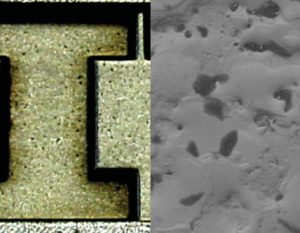
Figure 2 Cavity EDMed with an electrode exhibiting inconsistent microstructure

The impact of pinholes and pitting in the cavity is lessened with an electrode material consisting of small particles and a tight correlation in the range of particle size. Again, as seen in Figure 1, the structure of some of these samples are indicative to a wide range of particle sizes. The combination of small and large particles in the electrode microstructure further complicate the issue and the EDM gap is continually being adjusted through the sinker’s adaptive control. This adjustment is necessary to eliminate the potential of damaging the cavity as illustrated in Figure 2. This cavity was EDMed with an electrode exhibiting an inconsistent microstructure.

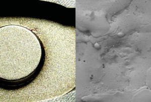
Conversely, Figure 3 was EDMed with an electrode exhibiting a consistent microstructure. Although both cavities were EDMed using the same machine parameters, the difference is significant.

Imperfections in the cavity caused by using the wrong electrode material must be removed through additional EDMing or polishing. This is necessary to remove any pits, pinholes, or blemishes that extend below the surface. Regardless if the polishing is done by hand or by a mechanical means, too much removal of stock will create the need to rework the cavity with welding and burning or remaking the cavity altogether. The same care must be taken in any reworking process to ensure enough material remains in the cavity to produce a surface area free of blemishes. The ideal situation is to

Figure 3: Consistent Electrode
Figure 3. Cavity EDMed with an electrode exhibiting consistent microstructure

produce an initial surface finish that requires minimal polishing or reworking of the cavity. In some instances, the finishing stage must be accomplished within the EDM with no polishing or added processes. Some details in the cavity limit the ability to hand work the surface finish due to fine detail such as thin ribs and cross sections or the requirement for sharp corners.

The electrode in Figure 4 is a good example of this. This electrode is for a medical component and contains detail too small for hand polishing. Doing so would eliminate critical tolerances and therefore requires the surface finish to be produced in the EDM machine. To be successful in this application, a fine grain, high-quality material must be used. To cut corners and select the electrode material based on price would yield less than satisfactory results.

Figure 4: Fine Electrode Detail
Figure 4. Fine electrode detail increases the importance of a quality material

DO NOT FOCUS ON PRICE

Selecting the proper electrode material to produce a fine surface finish is vital to the success of the application. It is important to understand which material has the potential to achieve an acceptable finish without the need for excessive handwork or polishing. By realizing the role that the microstructure of the material plays in producing fine surface finishes, the manufacturing costs of the mold can often be reduced. The most popular graphite electrode materials used for fine finish work fall within the Angstrofine and Ultrafine classifications. Materials within these classifications can be expected to have specific performance characteristics consistent with the microstructure it exhibits.

Using high-quality graphite can actually reduce the overall manufacturing costs. In this case, the old adage, “It takes money to make money” holds true. Sure, the high-quality graphite costs a little more than a lower quality material, however, the rewards of increased performance, finer surface finishes, and reduced requirements for hand polishing offset the extra cost of the electrode material. The cost of the electrode material is just a small portion of the mold cost, yet when it comes to cutting costs this is often the first area that gets affected.

The grade of electrode material used is a critical facet in the EDM process and it is important for the EDMer to become familiar with the numerous options available. With a myriad of graphite materials available for EDM, the EDMer can easily become confused on which is the proper material for a specific application. The bottom line is that for any application, a material with a consistent microstructure and uniformity between the particles and porosity offers predictable performance. When fine finishes are required, a small grain material produces finer finishes than large grain materials regardless of the microstructure uniformity. However, to receive the most return on the investment cost of the electrode, a small grain material with uniform microstructure will bring optimum results in the most critical applications.

FOR MORE INFORMATION

Please call your local distributor to learn what our premium graphite solutions can do for you. Visit poco.entegris.com/distributors for the location nearest you.
Week 2 EDM Graphite Buyer’s Guide

From Entegris Poco  Author: Rick Slimp


INTRODUCTION

Unless you have money to burn, time to spare, and a great mold repair team, never use words like “equivalent to” or “as good as” when purchasing your EDM graphite. These phrases or similar terms open the door for substitution of a lower quality inferior grade that will increase your frustrations in the electrode fabrication and EDM areas. If you do not specify exactly the grade you want delivered, you might as well open your wallet and prepare for a robbery. Blunt statements, but all too true.

Through the past three decades, I have been asked many questions concerning carbon and graphite. A question I used to get on a regular basis was, “Can you make white graphite?” I don’t get this one very often anymore, either dark grey/black is in style or they just got tired of hearing my attempt at a technical explanation on why white graphite is not a possibility. Another common question is, “Do you make pencil lead?” The answer is yes, if you don’t mind the pencil cutting through your paper and scratching your desk. On more than one occasion, I have been asked, “Where is your graphite mined?” A long explanation of natural graphite vs. man- made graphite is required.

More often I receive questions like these: “How do I know I am getting the grade ordered?”, “Is there a simple test I can do in my shop to determine the grade of graphite being supplied?”, and “With so many grades available, how do I know which grade is best for my EDM application?”

Too often our EDM applications engineers receive calls requesting technical assistance on a job where things are not going well in the electrode manufacturing area of the EDM machine, only to learn that the shop is using the incorrect grade of graphite for the application or they are not getting the grade they thought they had ordered. Often getting the correct electrode material gets the job back on track.


TESTING LAB

In the past 40 plus years, our lab has tested hundreds of manufacturers’ grades and possibly thousands more being sold as reseller house brands. These grades are each tested for a wide range of physical properties, microstructure, and EDM performance (end wear, corner wear, surface finish, and metal removal rate). There have been approximately 78,000 graphite samples tested to date and the records and photo chip for every sample are maintained. The photo mount for sample number one, taken in 1970, is safely stored for reference if needed.

This allows us to monitor changes in a grade over long periods of time and determine the manufacturer’s grade for materials being sold under house brand names. Want to know the physical properties of one of our grades produced in 1980? No problem; we have the testing results and the sample from that period in our lab. Need to know if another manufacturer’s grade or house brand grade has changed in the past few decades? We have the test results available and samples available to answer that question too.


GRAPHITE GRADES

Almost every manufacturer produces a series of grades for EDM applications. Some of the manufacturer grades are sold to EDM end users as the manufacturer’s grade. When buying a manufacturer’s grade, you often have more than one supplier offering the exact grade under the manufacturer’s grade name and you also have a known manufacturer in case a concern develops with the material. Knowing the manufacturer and the distributor is a benefit to the customer. A common practice of some manufacturers is to allow resellers/distributors to rename or house brand their grades. House branding removes the tie to a specific manufacturer and specific manufacturer grade. House branding makes the reseller/distributor a sole source for their house brand. The exact manufacturer’s grade may be sold as several other house brand grades, but the end users will not be aware that house brand A from company X is the same as house brand B from company Y, etc.

We do not allow our distributors to house brand our materials. When you order a specific graphite grade of ours it must be the same product regardless of the distributor chosen, the region of the world where you buy the graphite, or the length of time between your orders. Electrodes produced from our EDM-3® graphite ordered last week will perform just like EDM-3 graphite electrodes that have been in storage at a customer location for 20 years. The manufacturing process must be highly controlled and repeatable to generate consistency within a block, block to block, batch to batch, or decade to decade.

Almost a half century of highly controlled lab analysis indicates there are no grades that are exactly the same. Each manufacturing process yields a product with different physical properties, microstructure, and performance. In some cases the physical properties are similar, but the performance as an electrode material varies greatly. In other cases, there may be good EDM performance, but the material is too hard to machine into electrodes. To be a good EDM grade, the material must be very consistent, be capable of being machined to fine detail without chipping or wearing tools, and perform well in the EDM process. Excelling in all these areas defines a good EDM material.

In many cases the testing indicates the published specifications are highly exaggerated. For the most part, comparing published specifications is of little to no value since there is no policing of the specifications being published. Making buying decisions based solely on published specifications is not recommended.


GUIDELINES

I offer these simple guidelines when purchasing your EDM graphite requirements.

  1. Determine the material grade best suited for your application and know why you are selecting that grade. Help in selecting the correct grade for your application is available if you need
  2. Specify the exact grade you want and note “no substitution” on the quotation request, purchase order, email correspondence,
  3. Be on the lookout for words such as “like”, “equiva- lent”, or “type” on the quotation, acknowledgement, packing list, and invoice. Making it clear that “no substitution is allowed” will help assure that you are getting the exact grade you are ordering and for which you are paying.
  4. Know the company supplying your EDM graphite very If you are new to EDM, ask other shops what graphite supplier they are using and their experience with the company. If you get a call out of the blue, offering prices too good to be true, beware. There are many companies in the EDM supply business that have developed a very good reputation for honesty, integrity, and ability to service our industry. Select and buy from one of these companies. They will supply you the exact grade you order, since their good reputation and livelihood are at stake. These companies will gladly provide a “certification of grade” if requested.

If you have specified the exact grade being ordered, stated “no substitution” on the documents, ordered from a company with a good reputation in the industry, and you still would like more assurance that the grade you received is exactly what you ordered, we have a solution. We will test a sample of the material at no cost to you. It is not necessary to disclose the grade or the supplier when sending the sample.

We all know that graphite, for the most part, looks the same, feels the same, smells the same, and probably tastes the same. However, no two graphite grades are the same in terms of consistency, quality, and performance. Being an educated buyer will ensure that you are always getting the exact material needed and ordered.

FOR MORE INFORMATION

Please call your local distributor to learn what our premium graphite solutions can do for you. Visit poco.entegris.com/distributors for the location nearest you.
EDM Training Boosts Productivity

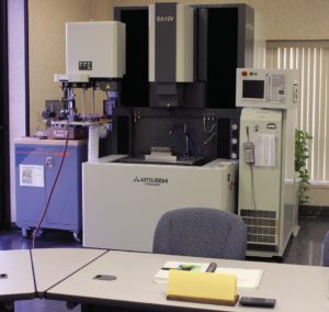
by Entegris Poco GraphiteEDM Machine Using Electrodes

Increasing the effectiveness of EDM operations does not come solely with technological improvements in the EDM sinker. This is one of many aspects needing to be considered when working to optimize EDM performance and increase productivity. Other areas of consideration include the type of dielectric fluid, tooling and electrode material used in the EDM applications. One area often overlooked or disregarded is the training required to make the most of the many factors affecting efficient operations.

A competitive company should seriously consider every opportunity to take advantage of technical training being offered by leading suppliers in the industry. This training is often at no charge with the only investment to the company being travel and salary. Even the shortest of training sessions provide the opportunity to recover any costs incurred in a very short time. A case in point includes a company engaged in EDMing – primarily carbide – and experiencing significant electrode wear and slow burn times. The wear and slow burn times demanded an increase in the volume of electrodes produced; therefore, not only adding to material cost, but significantly increased manufacturing costs for machining these electrodes.

The manufacturing cost limited profitability in this application, so the decision was made to send an employee to our EDM technical training session. One of the topics covered in the training included electrode material selection, honing in on the advantages of specific material when EDMing high thermally conductive metals. As it turns out, this company was purchasing the wrong type electrode material for EDMing carbide.

When working with metals of high thermal conductivity, the work-piece absorbs the spark energy almost instantly and limits the effectiveness of the EDM process unless changes are made specific to these type metals. In the case of this example, the electrode material used was a medium grade non-copper impregnated material and was selected primarily on a lower material costs than others available. The student realized during this training that copper impregnated electrode materials exhibit significantly lower electrical resistivity values than a non-copper impregnated material and allows for maximum spark intensity in the EDM cut. This not only increases the metal removal rate, but also allows for reduced electrode wear as well.

Another factor learned during this training session included the need to reduce the on-time to a length approximately equal to when the work metal begins to dissipate the spark energy in the cut. Any longer on-time will only serve to increase wear of the electrode without an effective metal removal rate. Upon the employee’s return, he began to implement the lessons learned during his time at the training. With sample material provided during the training, he began to experience immediate productivity improvements in the EDM. He claims his productivity has increased so much that the company has recovered the cost of the training and much more.

Be sure to contact us for more details on how your company can benefit from attending a training session — with both classroom and laboratory activities for the beginner or the experienced EDM operator — on the products you use in your EDM operations. Look for a program designed to help end users gain a better understanding on how to control the EDM process to achieve predictable results and one that enables you to return with practical information that can immediately be put to use on the shop floor.

FOR MORE INFORMATION

Please call your local distributor to learn what our premium graphite solutions can do for you. Visit poco.entegris.com/distributors for the location nearest you.
Driving Towards a 5.0 Class Status in Six Sigma

Contact Us About
Your Needs

© All Rights Reserved.